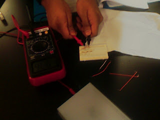
Thursday, March 15, 2012

Experiment: Nodal analysis

In the multiple sources, we should use the nodal analysis to identify the nodes, choose a reference node, and assign node voltages to the rest. Using  KCL analyze the current flow through the node, and KVL will be used to calculate the voltage drop.

In theoretical
(v1-v2)/Rc1= v2/RL1+ (v2-v3)/Rc2
(v4-v3)/Rc3= v3/RL2+ (v3-v2)/Rc2
put the value Rc1 =100ohm, Rc2 =Rc3=220ohm, RL1=RL2=1000ohm
Vb1=12v, Vb2=9V
V2=10.2554V, V3=8.674V
Ib1=0.0774A
Ib2=0.00148A


ComponentNominal ValueMeasired ValuePower or current rate
Rc110099.8
Rc2220219
Rc3220218
RL11000981
RL21000982
Vb11212.172A
Vb299.112A

Variable Theoretical Measured percent error
Ib1 17.44mA 18.65mA 6.93%
Ib2 1.482mA 1.58mA 6.61%
V2 10.255V 10.36V 1.02%
V3 8.674V 8.75V 0.88%

step 6
1)actual power
Pb1=0.227W
Pb2=0.0144W

2) if v2=v3=9v, the new Vb1 and Vb2
Vb1=9.9V
Vb2=11.198V

actual voltage and current
V2=8.89V
V3=8.98V
Ib1=8.4mA
Ib2=9.5mA

Monday, March 12, 2012

Lab: Freemat to calculate circuits.

This experiment train us to use the freemat to do the circuits.

;There have some useful way to us the freemat.

make the vector([1 2]) or matrix([1 2: 3 4])
array operation(.* , ./ , .^)

create a arithmetic sequence [start value: difference: end value] such as [0:0.01:2*pi]
using the that sequence as x axis and y function to plot the graph
x=0:(pi/10):pi*2
y=sin(x)
plot(x,y)

In the end of the lab, we use the matrix to solve the current, voltage, and power of the circuits
use the KCL to get the i3=i1+i2
then KVL to get V1=i1R1+i3R3, V2=-i2R2-i3R3
put the value from KCL i3=i1+i2 into KVL
we can get the
V1=i1R1+(i1+i2)R3=(R1+R3)i1+R3i2
V2=-i2R2-i3R3= -i2R2-(i1+i2)R3= -R3i1 -(R2+R3)i2
put the constant value in the question
v=[15:7]
R=[30 10:-10 -15]
i1,i2 = 0.8429A, -1.0286A
so i3= -0.186A

Wednesday, March 7, 2012

Experiment: introduction to biasing

In this experiment, we connet two led in parallel and get the data of its voltage and currents. Then calculating the error with the theoretical value and actual value.

step 1:
calculate the theoretical value.
RLED1: V=5volt and 22.75mA, so it has 219.78ohm
RLED2: V=2volt and 20mA, so it has 100ohm
V power= 9.07V
Theoretical value Current Voltage Resistance power
R122.75mA4V175.82ohm0.091w
R220mA7V350ohm0.14w

The resistor didn't have the valur of 175.82 or 350ohm, so connecting in series to get a close value.
R1= 14.9+147.6+99=174.9 with the reisitance on the board, we get R1=172.9ohm
R2= 98+98+149.3=345.3 , but we use the multimeter  get R2=344.1 ohm


step 7:the actual data get from the circuit.
config I LED1 V LED1 I LED2 V LED2 Isupply
114.6mA6.5V19.9mA2.15V34.5mA
214.5mA6.5Vxx14.5mA
3xx19.9mA2.15V19.8mA

The LED 1 seems not a 5V LED.
and the resist is 448.27 different with the theoretical value 219.78ohm
LED 2 resistance =108.04ohm


step 9:
a) (0.6A-0.2A) hr/ (22.75+20)mA= 9.357 hr
b) LED 1 error%= (14.6-22.75)/22.75*100=35.82%
    LED 2 error%= (19.9-20)/20*100=0.5%
 The LED 1 is not a 5V LED, the resistance is too large than the theoretical value.
 The  LED 2 is very close to the theoretical value.
c) LED  efficiency= [power out of led1(14.6mA*6.5V)+power out of led2(19.9mA*2.15V)]
  divided by power of supply(9.07V*34.5ma)= 44%
d) If we make the led1 to 5v(reduced the curreny pass through the LED1)
   The current flow to LED1 will be 5V/448.27ohm=11.15mA
   The current flow to LED2 will be 2V/100ohm=20mA
The power out = 5V*11.15mA+2V*20mA=0.09575
The total power= 6V*(11.15+20)mA=0.1869
efficiency= 0.09575/0.1869=51.23%
The efficiency increase.
When the power supply be the 2V or 5V, the efficiency will have highest value for not power lost on resistors except the resistance in the cable.

Monday, March 5, 2012

experiment:Introduction to DC circuits

In this experiment, building a simple dc circuit, setting the
we used the DC circuit to calculate the power by using P=IR^2 from the cable and resistor, and then using formula P=IV to get the power from power supply.


1. load is rated to consume 0.144w and supplied 12v, by R=V^2/p=144/0.144= 1000ohm
The resistor color of 1000 ohm is brown black Red.
Then using the multimeter to measure the resistor and get the measured value is 981ohm

2. using the multimeter to get the measured value of power supply, V= 12.18volt
3. the resistor box is 78 ohm

The data get from the step 6 perform the experiment.
using the multimeter connet to the circult.
Vload = 11.24volt
Ibatt= 11.4mA
Step 8 make data calculations.
A)

B)
Power to the load =Vload*I= 0.128136 watt
power to the cable= I^2*R= 0.010137 watt
the efficiency= Pout/(Pout +Plost)=Pload/(Pload+ Pcable)= 92.66%
C)
we didn't exceeding the power capability of resistor box. for I=V/(R+Rbox)
Pbox=I^2=V^2/(Rbox*(R+Rbox)^2)
The power of box will be bigger when Rbox very small.
D)
78ohm/ (0.3451ohm/m)[AEG#30] =226.021m (all cable)
E)

F)
The volt down (48-36)=12volt, use R=V/I=12/10=1.2ohm
the resistance of cable is 1.2ohm


AWG Resistance(ohm/ft) Cable maximun length
10 .00118 1016.9
12 .00187 641.7
14 .00297 404.04
16 .00473 253.7
18 .00751 159.8
20 .0119 100.8
22 .0190 63.2
24 .0302 39.7
26 .0480 25
28 .0764 15.7