Monday, May 28, 2012

Freemat: complex number

Purpose: using FreeMat to do the complex number question, and using it to do the AC circuit calculation.

1 Let A1=3+2j, A2= -1+4j, B= 2-2j, Determin C=(A1*B)/A2

c =-1.0588 -2.2353j


2.change the rectangular to polar form.
abs(complex number) will get it sqrt(R^2+X^2), and angle(complex number) will get the angle of it by radius.

c=2.47 ∠ -115.35°


3.redo item 1 and 2 for D=(A1+B)*A2

d= -5+20j
  = 20.62 ∠ 104.04°


4. do the lecture part
(8 + j8)I1 + j2I2 = j50
j2I1 + (4 − j4)I2 = − j20 − j10


I1=2.0588+2.9412j
   = 3.59 ∠ 55.01°
I2=5-3.5294j
   = 6.12 ∠ -35.22°

Impedance and AC analysis I

Purpose: analyze impedance the inductor and capacitor in a AC circuit.

Background: Introduce  that a real inductor model must include a series resistance to account for the resistance of the many turns of wire and thus appears as series.

Zl.real = RL+ jωL
 Vin/Iin= Zreal=sqrt(RL^2+ jωL^2)


steps:
step 1. RL=3.4Ω
step 2.
Rext=68.5Ω
DMM reading: 4.54V

Vin= 4.5V
I in,rms=87.3mA
f=20kHz

-make computations to get inductor value.
Z=V/I=4.5/87.3m= 51.546Ω
Z=sqrt(Rext^2+RL^2+(jωL)^2)
ω=20k*2π=1.257*10^5
Z=sqrt((68.5+3.4)^2+(jωL)^2), 51.55^2=71.9^2-(1.257*10^5)^2*L^2
L^2=1.59*10^-7, L=4.0*10^-4H=0.4mH
L=0.4mH

step 3. Investigating a series RLC circuit

make the inductor and capacitor's impedance cancel up.
X= ωL-1/ωC
ωL=1/ωC.
C=1/(ω^2*L)= 1/((1.257*10^5)^2*0.4m)=158nF
The capacitot we use in the circuit is 151nF

The frequence we get max frequence is 12.7kHz
Vpp.ch1=21.2
Vpp.ch2=19.5
Δt=19.46μs
ΔΦ=19.46μ*2*12.7k*360=88.971

Vin(V) Iin(mA) Zin
5kHz 5.78 29.3 197.2696
10Khz 5.22 65.1 80.18433
12.7kHz 4.95 73.5 67.34694
30kHz 5.56 23.8 233.6134
50kHz 7.62 1.7 4482.353

Follow-up question.
1.ans: when in maximum current, the ωL=1/ωC and make the Zeq be the minimum. Therefore, I=V/R and make the current be the maximum.
2.
3.ans:The circuit will me more capacitive(ωL<1/ωC)
4.ans:The circuit will me more inductive(ωL>1/ωC)


AC signals #1

Background: This exercise will focus on measuring the phase difference between AC sinusoidal singals at the same frequency

ΔΦ=tx*ω*(180/π)


Part A.
;2.Vrms= 0.3536V
;3. DMM measured RMS Vrms=0.318
6. f= 1000Hz, C=100nF
theory(100nF)Zcap=  1/2*pi*1000Hz*100nF=1591.55Ω
real(102nF)Zcap= 1/2*pi*1000Hz*102nF=1560.34Ω

8.
a) Vcap,pak=pk=0.852V
b) Vcap,rms=0.256V
d) tx=105.41 μs
e) Φ=105.41μ*2π*1000*180/π=37.9476°
f) CH1 lead.

Part B
increase f from 1kHz to 10kHz
2. Zcap=156.034Ω

3
a)Vcap,pk-pk=0.154
b)Vcap.rms=0.033
d)tx=237.8μs
e)Φ=237.8μ*2π*1000*180/π=85.608°

Part C
change resistance to 10kΩ, and return the f to 1kHz
a)Vcap,pk-pk=0.166
b)Vcap.rms=0.049
d)tx=221.62μs
e)Φ=221.62μ*2π*1000*180/π=79.78°
f)Rbox=3700Ω
g)Vcap.rms=0.119
h)tx=189.19μs
i)Φ=189.19μ*2π*1000*180/π=68.11°

Part D
2 in low frequency range is the capacitor voltage amplitude greatest
3.in high frequency range is the capacitor voltage amplitude smallest
 Vcap=Vs*Zcap/(Zcap+Zres), so the Zcap increase, the Vcap will increase.
 Zcap=1/(ωC), so the ω decrease the Zcap will increase.
4. high pass filter, the CH2 amplitude is less than CH1.
5. ΔΦ=tx*ω*(180/π)=tx*2*f*180, so the frequence increase the Φ will increase.
6.

Practical integrator op amp

Purpose: in this experiment, we connect op amp with the first order circuit, and draw the graph with different waveforms.


Sketch the input and output waveforms fro 1kHz sin wave, trangle wave, and square wave input.
sine wave
square wave
trangle wave

Question
Note that 10MΩ resistor is not in the ideal integrator circuit. what is there for? (think about what would happen if a small DC component in the input waveform. waht would integrating this constant do after a short time?) what happens when it is removed?
A: If we remove the 10MΩ resistor, the Rf will become the value of capacitor. In the become of charge capacitor, the resistance of its is infinite, so the gain A will become infinite/Rin= infinite and get error. Inserting a 10MΩ resistor will make the gain =infinite*10M/(infinite+10M)= 10M, and it is an acceptance gain.


Experiment: Capacitor charging/discharging

Purpose: Learn the capacitor are components that storing the energy via the electric field, and we will consider charging and discharging a capacitor.

The circuit have the charge side with the voltage source connect in the begining. After the charging, switching to the discharging circuit.


Charging:
Vc(t)=Vo(1-e^(-t/RC))
Ic(t)=(Vo/R)*e^(-t/RC)
Discharging:
Vc(t)=Vo*e^(-t/RC)
Ic(t)=-Io*e^(-t/RC)


Problems:
QThe Vs is 9V, and we want charging interval of about 20s storing 2mJ in the capacitor, and then discharging the capacitor in 2s.
1.for the W=V^2*C/2, C=2W/V^2=5m/81=61.73μF
2a.We want Vc(t) charging to 99% of the Vo, when 1-e^(-5)=99.3%
so -5=-20/R*61.73μ, and R =64.8kΩ
2b.peak current= Vo/R= 9/64.8k=0.1389mA
and peak power =VcIc=9*0.1389=1.25mW
3a. -5=-2/R*61.73μ, R=6.48kΩ
3b. peak current= Io= Vo/R=9/6.48k=1.389mA
P=IV=1.389m*9=12.5mW

Measure data.
Rcharge = 65kΩ
Rdischarge = 6.47kΩ
C=63.6 uF
The maximum Voltage is different with the ideal data.

Charging
The V=8.476, 8.476=9*Rleak/(Rleak+65k), Rleak=1.23MΩ


Discharging 


Experiment: Op amp applications

Purpose: This time we use the AS35 which the amplifier change its gain from its temperture connect to the Lm741 circuit, and it has the change scale factor of 10mV/ ºC. We should build the circuit and measure the Vc, VF, and Vref to get the relation of these value. Then calculating temperture with the formula.

The Lm741 part is the difference circuit
so the vf=(1+R2/R1)vc -(R2/R1)*Vref
The formula covert ºF to ºC is ºF=1.8ºC+32
If we assume the 1+R2/R1=1.8, the R2/R1 will be 0.8.
Then make -(R2/R1)*Vref=0.32, so the Vref= -0.4V
The relation of vf, vc, and vref will be the formula of temperture covert.

Data measures:
R1=2.12kΩ
R2=1.75kΩ,  R1/R2=0.825.
Vref=-0.404V
Vc=0.237V
Vf=0.765V

Calculation:
Tf= (1.825*0.24+0..825*0.404)*100=76.58ºF
The room temperture is 23ºC= 73.4ºF
error %=(76.58-73.4)/73.4=4.33%

Experiment: Op amplifiers 1

Purpose:  In this experiment, we try to use the operational amplifiers to build the circuit and learn how to amplify the voltage in the circuit. The inverting amplifier circuit will give a A= -Vout/Vin.

Steps:
we assume the Vin= 1V and Vout= -10V, so A= -(-10)/1=10. In addition, we must make the input current less than 1mA, so the input resistor =1V/1mA= 1kΩ and output resistor= 10*1k=10kΩ.


The 5 volt power source to get 1v, we make the Rx=286Ω and Ry=57.6Ω


Nominal value Measured value  Rate
Ri 1kΩ 981 0.25
Rf 10kΩ 9830 0.25
Rx 288Ω 286 0.125
Ry 58Ω 58.7 1
V1 12V 12.15
V2 12V 12.14

Then measure the value of Vout,Vin, and Vrf

step5A:
Vin Vout(M) Gain(C) Vin(M) Iri(C) Vrf(M)
0 -0.32 null 0.02 0.0000204 0.34
0.25 -2.91 11.64 0.27 0.275 2.85
0.5 -5.31 10.62 0.52 0.53 5.33
0.75 -7.8 10.4 0.77 0.785 7.86
1 -9.97 9.97 0.99 1.01 10.02
step5B:
Iv1=1.51mA
Iv2=0.49mA

Pv1= 12.15*1.51m=18.35mw; Pv2= 12.14*0.49m=5.95mw
It satisfies the power supply constraint to supply no more than 30mW.


Thursday, March 15, 2012

Experiment: Nodal analysis

In the multiple sources, we should use the nodal analysis to identify the nodes, choose a reference node, and assign node voltages to the rest. Using  KCL analyze the current flow through the node, and KVL will be used to calculate the voltage drop.

In theoretical
(v1-v2)/Rc1= v2/RL1+ (v2-v3)/Rc2
(v4-v3)/Rc3= v3/RL2+ (v3-v2)/Rc2
put the value Rc1 =100ohm, Rc2 =Rc3=220ohm, RL1=RL2=1000ohm
Vb1=12v, Vb2=9V
V2=10.2554V, V3=8.674V
Ib1=0.0774A
Ib2=0.00148A


ComponentNominal ValueMeasired ValuePower or current rate
Rc110099.8
Rc2220219
Rc3220218
RL11000981
RL21000982
Vb11212.172A
Vb299.112A

Variable Theoretical Measured percent error
Ib1 17.44mA 18.65mA 6.93%
Ib2 1.482mA 1.58mA 6.61%
V2 10.255V 10.36V 1.02%
V3 8.674V 8.75V 0.88%

step 6
1)actual power
Pb1=0.227W
Pb2=0.0144W

2) if v2=v3=9v, the new Vb1 and Vb2
Vb1=9.9V
Vb2=11.198V

actual voltage and current
V2=8.89V
V3=8.98V
Ib1=8.4mA
Ib2=9.5mA

Monday, March 12, 2012

Lab: Freemat to calculate circuits.

This experiment train us to use the freemat to do the circuits.

;There have some useful way to us the freemat.

make the vector([1 2]) or matrix([1 2: 3 4])
array operation(.* , ./ , .^)

create a arithmetic sequence [start value: difference: end value] such as [0:0.01:2*pi]
using the that sequence as x axis and y function to plot the graph
x=0:(pi/10):pi*2
y=sin(x)
plot(x,y)

In the end of the lab, we use the matrix to solve the current, voltage, and power of the circuits
use the KCL to get the i3=i1+i2
then KVL to get V1=i1R1+i3R3, V2=-i2R2-i3R3
put the value from KCL i3=i1+i2 into KVL
we can get the
V1=i1R1+(i1+i2)R3=(R1+R3)i1+R3i2
V2=-i2R2-i3R3= -i2R2-(i1+i2)R3= -R3i1 -(R2+R3)i2
put the constant value in the question
v=[15:7]
R=[30 10:-10 -15]
i1,i2 = 0.8429A, -1.0286A
so i3= -0.186A

Wednesday, March 7, 2012

Experiment: introduction to biasing

In this experiment, we connet two led in parallel and get the data of its voltage and currents. Then calculating the error with the theoretical value and actual value.

step 1:
calculate the theoretical value.
RLED1: V=5volt and 22.75mA, so it has 219.78ohm
RLED2: V=2volt and 20mA, so it has 100ohm
V power= 9.07V
Theoretical value Current Voltage Resistance power
R122.75mA4V175.82ohm0.091w
R220mA7V350ohm0.14w

The resistor didn't have the valur of 175.82 or 350ohm, so connecting in series to get a close value.
R1= 14.9+147.6+99=174.9 with the reisitance on the board, we get R1=172.9ohm
R2= 98+98+149.3=345.3 , but we use the multimeter  get R2=344.1 ohm


step 7:the actual data get from the circuit.
config I LED1 V LED1 I LED2 V LED2 Isupply
114.6mA6.5V19.9mA2.15V34.5mA
214.5mA6.5Vxx14.5mA
3xx19.9mA2.15V19.8mA

The LED 1 seems not a 5V LED.
and the resist is 448.27 different with the theoretical value 219.78ohm
LED 2 resistance =108.04ohm


step 9:
a) (0.6A-0.2A) hr/ (22.75+20)mA= 9.357 hr
b) LED 1 error%= (14.6-22.75)/22.75*100=35.82%
    LED 2 error%= (19.9-20)/20*100=0.5%
 The LED 1 is not a 5V LED, the resistance is too large than the theoretical value.
 The  LED 2 is very close to the theoretical value.
c) LED  efficiency= [power out of led1(14.6mA*6.5V)+power out of led2(19.9mA*2.15V)]
  divided by power of supply(9.07V*34.5ma)= 44%
d) If we make the led1 to 5v(reduced the curreny pass through the LED1)
   The current flow to LED1 will be 5V/448.27ohm=11.15mA
   The current flow to LED2 will be 2V/100ohm=20mA
The power out = 5V*11.15mA+2V*20mA=0.09575
The total power= 6V*(11.15+20)mA=0.1869
efficiency= 0.09575/0.1869=51.23%
The efficiency increase.
When the power supply be the 2V or 5V, the efficiency will have highest value for not power lost on resistors except the resistance in the cable.

Monday, March 5, 2012

experiment:Introduction to DC circuits

In this experiment, building a simple dc circuit, setting the
we used the DC circuit to calculate the power by using P=IR^2 from the cable and resistor, and then using formula P=IV to get the power from power supply.


1. load is rated to consume 0.144w and supplied 12v, by R=V^2/p=144/0.144= 1000ohm
The resistor color of 1000 ohm is brown black Red.
Then using the multimeter to measure the resistor and get the measured value is 981ohm

2. using the multimeter to get the measured value of power supply, V= 12.18volt
3. the resistor box is 78 ohm

The data get from the step 6 perform the experiment.
using the multimeter connet to the circult.
Vload = 11.24volt
Ibatt= 11.4mA
Step 8 make data calculations.
A)

B)
Power to the load =Vload*I= 0.128136 watt
power to the cable= I^2*R= 0.010137 watt
the efficiency= Pout/(Pout +Plost)=Pload/(Pload+ Pcable)= 92.66%
C)
we didn't exceeding the power capability of resistor box. for I=V/(R+Rbox)
Pbox=I^2=V^2/(Rbox*(R+Rbox)^2)
The power of box will be bigger when Rbox very small.
D)
78ohm/ (0.3451ohm/m)[AEG#30] =226.021m (all cable)
E)

F)
The volt down (48-36)=12volt, use R=V/I=12/10=1.2ohm
the resistance of cable is 1.2ohm


AWG Resistance(ohm/ft) Cable maximun length
10 .00118 1016.9
12 .00187 641.7
14 .00297 404.04
16 .00473 253.7
18 .00751 159.8
20 .0119 100.8
22 .0190 63.2
24 .0302 39.7
26 .0480 25
28 .0764 15.7

Wednesday, February 29, 2012

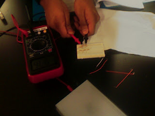
Review Exercise: using a multimeter

     In the first part, using the multimeter to test different resistors, and to know different color ring on the resistors to calculate the value of resistance.
The data get from the experiment:
Resistor Colors Value form Colors      Measured Value
Brown Read Read
1200
1186
Orange Orange Brown
330
327
Red Red Brown
220
216
Orange Orange Read
3300
3280

         Then we try the make the circuit. Follow the circuit picture of the manual, the LED long leg side connect the positive and short one line to the negative side. In the middle of circuit, the units connecting are parallel. Two other side with positive and negative sides are perpendicular.  
         This experiment make us to use the multimeter which we will use all this semeseter, read the resistors, and make a simply circuit.
    I don't get the picture of the experiment, and I will attach it when I get it.